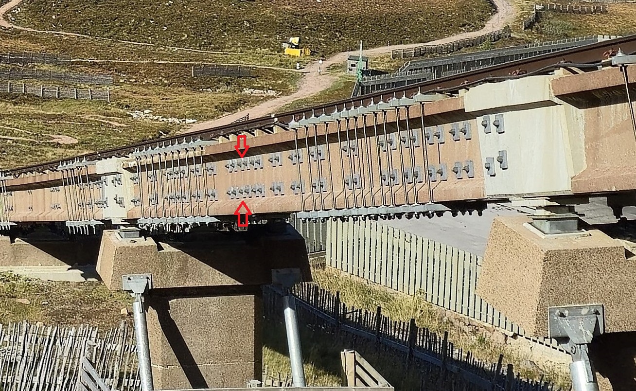
This picture of two piers below the passing loop show just how bad things are. There are 47 brackets on the two “I” beams between those piers and the two insitu joints have been rebuilt. The beam in the photo was found to be delaminating in 2017 and the calcite bleed can still be seen (to the left of the top red arrow). Note also the rows of new plates (between the red arrows) on the upper beam compared to the one further down also indicating major strengthening between the two beams. The differing quality of repairs is also evidenced by the finish to the studding on the brackets. All the upper brackets just left of pier 52 are cut to length and capped, the ones either side of pier 51 left as fitted! No attempt to keep the job tidy.
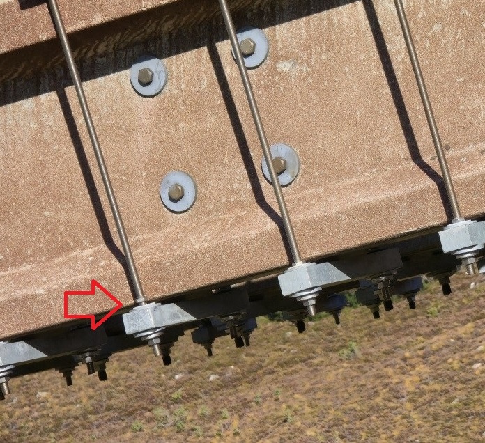
Another loose nut! This nut may not be doing anything, as explained in my last post (see here) but was first photographed on 13/07/2025.
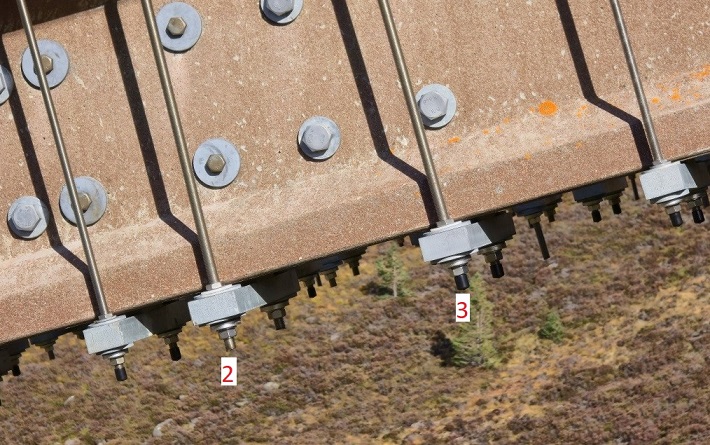
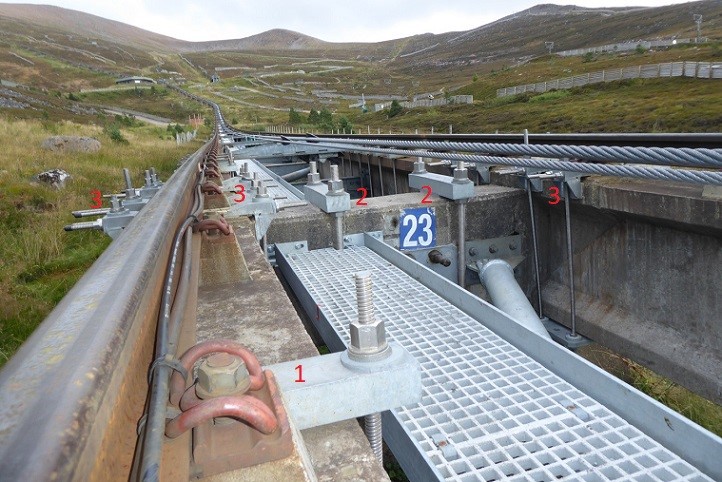
This “I” beam has different thicknesses of studding (the metal rods), most easily seen in the shadows, but the second and third metal bars are also bigger than the ones on either side and have large plastic washers above them. Does this require different levels of tensioning?
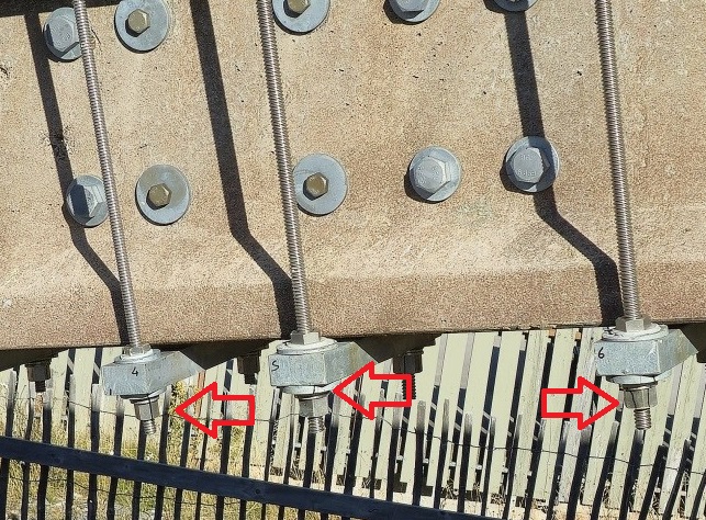
Again studding not capped but it would appear that someone has or is trying to simplify an inspection by putting a black line (strike marks) from the washer down to the nut. Why then wasn’t every bracket marked like this? Did they run out of marker pens? There is an easier way to check the tension in all the brackets, a hammer commonly known in the vehicle trade as a “toffee” hammer or more accurately a 4oz panel pin or cross pein hammer.
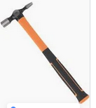 Simply tapping any bolt, nut or length of studding will produce a sound. If the tension is high it will be a high pitched noise, anything that is loose i.e. not under tension, will be just a dull thud, also all studding should make the same high pitched sound, but this is only a very basic test confirming tension in a length of studding. [If you have ever seen a guitar being tuned it is done one string at a time. Turning the tuning peg increases or decreases the pitch of the sound produced by a string. The tighter or greater the tension in the string the higher the pitch].
In the eighth post of this series I said I would come back to what I consider to be a more serious issue.
Working from a video from 2023 I previously counted approximately how many brackets were fitted as part of the strengthening works and found @ 1429. I have now checked this figure with the help of a new Youtube video (see here) and found 1426. This fact that almost the same number of brackets were visible in both videos shows no extra brackets were fitted between August 2023 and December 2024.
The different type of brackets break down as follows:
Type 1Bkts 908. No. of lengths of studding = (2 x 908) 1816
Type 2 Bkts 182. “ “ “ “ “ = (2 x 182) 364
Type 3 Bkts 336. “ “ “ “ “ = (8 x 336) 2688
Total Bkts 1426. Total Studding………….. = 4868
Now consider these numbers:-
First. The minimum number of nuts needed to secure every length of studding is (2 x 4868) 9736, however, it is obvious from the photos that most brackets have at least 3 nuts some even 4 so somewhere in excess of 14,604 nuts.
Second. 4,868 lengths of studding which have to be properly tensioned and maintained at that tension!
Third. Every piece of studding requires two stainless washers and two flanged bushes, another (4 x 4868) 19,472 parts! And that’s before adding in all the tapered washers and some of these parts being doubled up!
Fourth. This is probably the most important issue, the fitting of the tapered washers.
The majority of Type 1 and Type 2 brackets are strengthening “I” beams and insitu beams on which the top width is the same as the bottom. No tapered washers necessary, no problem.
Then there are other Type 1 brackets which have to be adapted for Type 2 Beams, 400mm top/340mm bottom, and Type 3 beams 500mm top/340 bottom. These require tapered washers to compensate for the angle of the studding (see here).
To compound the problem there has to be at least two different lengths and diameters of studding for Type 3 brackets, which are to strengthen the insitu beam joint where it meets the “I” beams, as the width of the top flange width of the insitu joint depends on which size of beams are being joined. It also requires a different degree of taper on the tapered washers. Without excellent quality control there is considerable scope for the repairs to have gone wrong.
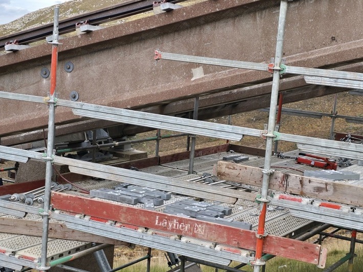
All of this raises yet another question to which HIE and CM(S)L have not commented. The funicular was closed in August 2023. On 04/10/2024 the majority of the brackets were lying on the ground or on the scaffolding some even lying on top of the “I” beams. This can be seen in the next photo.
Yet by 20/12/2024, as can be seen in the next photo,all the brackets had been replaced, presumably tensioned according to the COWI design , and the scaffolding had been removed.
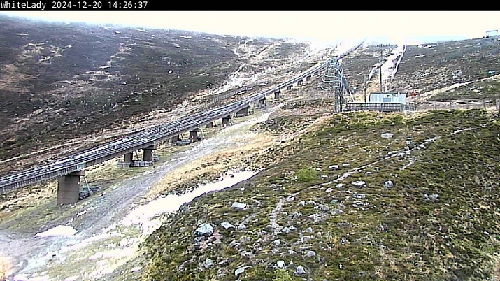
SINCE THEY MANAGED TO REPLACE THE BRACKETS, TENSION THE STUDDING AND REMOVE THE SCAFFOLDING IN 10 WEEKS WHY DID IT TAKE HIE 14 MONTHS TO REMOVE THE BRACKETS?
This lost circa year’s revenue including a whole winter season when there was good snow conditions.
Tensioning is quite a complicated process and requires special equipment and trained operatives. The whole idea is rather than use a wrench or spanner to tighten the nuts on the studding, the nut is fitted to the studding which is then stretched, using the special equipment, until the required tension is obtained and then the nut is tightened BY HAND ONLY. Releasing the tensioning equipment locks all the parts in place. The COWI specifications require tensioning to be carried out on all lengths of studding on any one bracket at the same time in increments of 25%, then up to 50%, then 75% and finally 100%.
But that isn’t all. On the Type 3 brackets where there are two different sizes of studding strengthening the Insitu joints, the tensioning is carried out in a set sequence after the brackets are lightly assembled.
(1) The smaller (horizontal) studding underneath the rails has to be tensioned in three increments to 75% of the required setting, then,
(2) The larger (vertical) studding is tensioned in three increments to 75% of the required setting, followed by
(3) The smaller studding being tensioned to 100% or full tension, and finally.
(4) The larger studding is tensioned to 100%.
As you can see this is quite a complicated procedure. Once all the studding and brackets on the funicular are tensioned to the correct setting how on earth is anyone going to know if the tension has altered UNLESS they have this special equipment and knowledge OR a bracket comes loose for whatever reason?!
That raises the question whether it Is possible to use this tensioning equipment from the maintenance walkway or if scaffolding is needed? I don’t know the answer to that as I have never seen the equipment involved or been instructed in its use, but presumably for health and safety, a stable work platform will be needed for all future adjustments.
Conclusion
I have been discussing the repairs with John Carson, the Skye bridge engineer. Speaking to the Press and Journal last week (see here) he stated “This structure’s not going to last 25 years”. “It might last 25 months.”
HIE could of course keep chucking money at the funicular – it is likely to require significant sums of money to keep the brackets at the right tension – and it might take a catastrophic failure before HIE or the Scottish Government change course.
The reason for this failure is that at the end of the day concrete was completely the wrong material to be used in such extreme and harsh conditions. It was reported to be in “poor condition for its age” in 2015, has now been deteriorating for another 10 years and will continue to deteriorate until sometime in the future, which no one can predict……..!

I’m not an engineer but I can recognise a dogs dinner when I see one……