Introduction to the current problems
Prior to the funicular returning to service on 27th February (see here) Highland and Islands Enterprise (HIE) made this announcement on 5th February (see here):-
“Staff at Cairngorm Mountain have today (Wednesday 5 February) begun a series of maintenance activities on the electrical, mechanical and hydraulic systems that govern the movement of the two funicular carriages up and down the 1.8km viaduct.
Later this week, an engineer from Swiss funicular specialist Garaventa, who supplied and maintain the carriages and control system, will join the local team to carry out scheduled annual inspections of the mechanical systems…………………
Meanwhile, remediation works are continuing on the viaduct structure, led by Balfour Beatty on behalf of mountain estate owner Highlands and Islands Enterprise (HIE).
Although the remediation programme was substantially completed before Christmas, inspections identified a range of items requiring further work and teams from Balfour Beatty returned to the site early in January.”
This was followed by a further announcement on 2nd May (see here):-
“The funicular is due to be out of service from Monday 12 May until Monday 2 June 2025 while the company’s in-house engineering team carries out works including rail grinding, gearbox repairs, undercarriage lubrication, and testing and inspection of the rail welds.
At the same time, Balfour Beatty, working on behalf of estate owner Highlands and Islands Enterprise (HIE), will return to complete their programme of remediation works on the railway viaduct.
CMSL usually carries out annual maintenance on the funicular in November, but has brought the timescale forward this year to run in parallel with the remediation programme and minimise inconvenience to visitors.”
Note how HIE aimed to “minimise inconvenience to visitors” by closing for a period which included a holiday week!
Then, more recently, this announcement on the Cairngorm Mountain (Scotland) Ltd website of 10/09/2025:-
It would appear that the once a year maintenance has now become twice a year or possibly even three times a year maintenance! Maintenance costs doubling or even trebling?
If “inspections identified a range of items requiring further work” why were these not completed in the May shutdown, or is it that more “items” have been “identified” since May?
The design of the repairs
The initial proposals from COWI, who designed the repairs, was that the concrete beams supporting the funicular should be replaced by steel, which is how the funicular was designed in the first place (see here). But HIE dismissed this and asked them to come up with another option, hence the multiple metal brackets designed to hold the concrete beams and is situ joints.
In several conversations I have had with John Carson and other civil engineers the general consensus of opinion is that the strengthening brackets were appropriately designed by COWI to hold the crumbling concrete together. It appears, however, that they are not doing what they were designed to do, so what is going wrong? I believe there are several issues which I will explain in two posts picking up on my series on “Will the repairs to the Cairngorm funicular work?” from four years ago (see here).
On 03/09/2020 I sent a Freedom of Information request to HIE for the COWI report and finally received a response on 11/12/2020 after appealing against an earlier refusal. The report I received showed the repair design as follows:
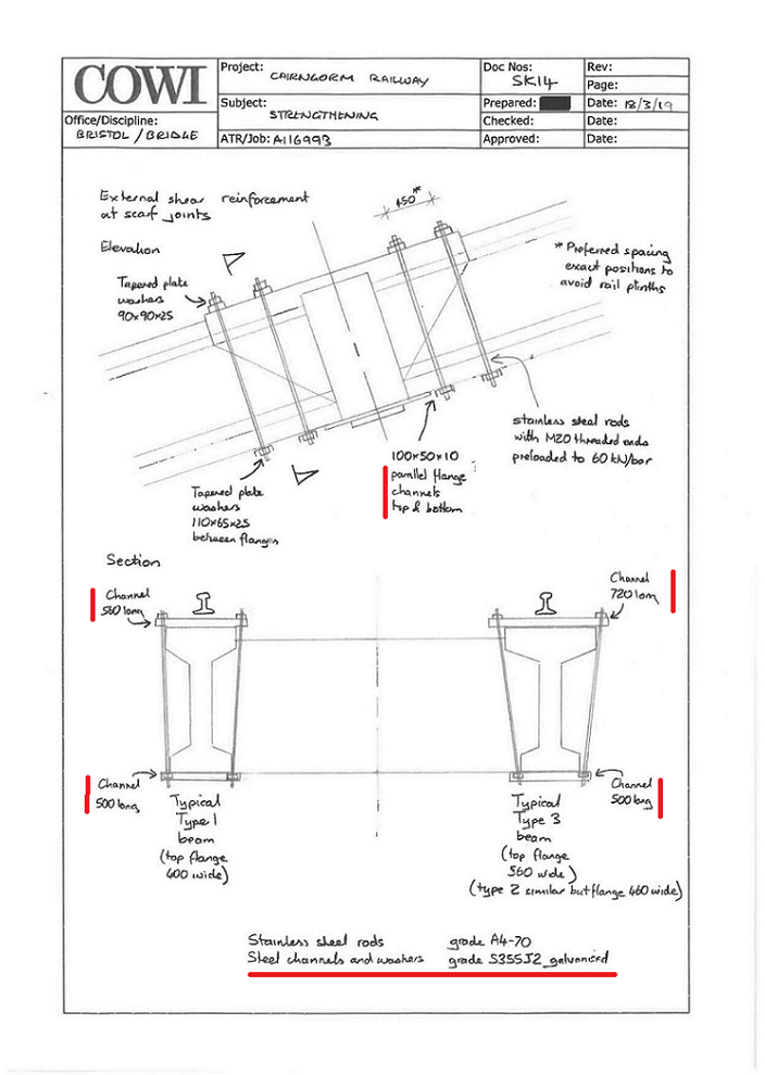
Note the use of channel.
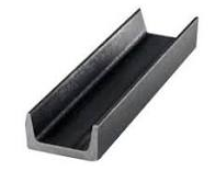
The picture is of 100mm x 50mm steel channel, one component of the brackets COWI originally designed for the repairs. Each end of the channel would be drilled to accept the studding with one length on top of the insitu joints/ beams and the other underneath. The widest part of the channel, 100mm, to sit against the concrete to spread the load as the studding is tensioned.
However, after visiting the funicular this year the actual repairs appeared significantly different to this design so 08/05/2025 I made another FOI request to query the design of the repairs and what had been actually done. HIE initially denied any changes had taken place, but, on 09/06/2025 I appealed their decision and on 09/07/2025 HIE finally released the drawings. These showed the brackets and studding which are fitted to the insitu joints plus associated instructions which were included in a report by COWI dated 26/10/2021. I have numbered them (a) to (d):
(a) Side on view
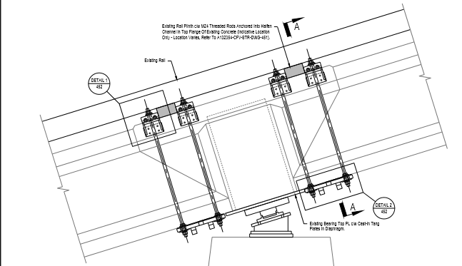
This shows metal plates instead of channel at the bottom of the in-situ joints and brackets at the top which are joined together across the beam by two further pieces of metal studding
(b) Birds eye view down onto top of insitu joint
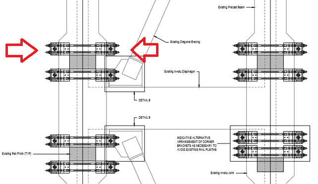
This clearly shows how the brackets at the top of the joint were to be connected by two lenghts of studding
(c) Section view
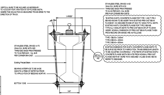
(d) Construction sequence
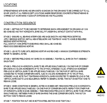
There were seven stages to the construction sequence making the repairs far more complicated
The design around the insitu joints was probably changed from channel to brackets as there was not enough clearance under the rails for the depth of the channel which was 50mm.
In order to work the studding needs to be tensioned correctly, too much and the concrete breaks as here, too little and the brackets don’t do the job they are supposed to do.
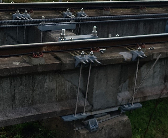
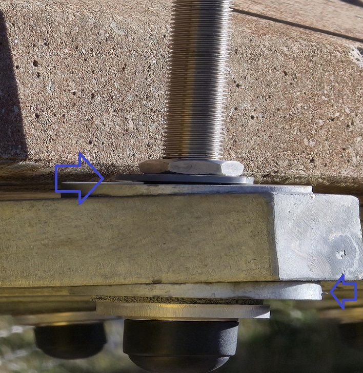
The changes and issues are further illustrated by the following photos taken on Wednesday 24/09/2025 by Dr Gordon Bulloch and respected civil engineer John Carson.
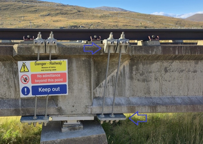
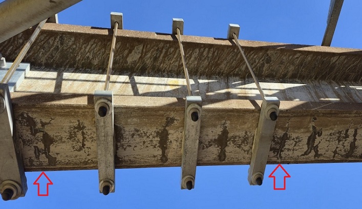
The brackets and studding which replaced the channel makes assembly and tensioning more complicated. There are eight lengths of studding around this insitu joint instead of four and each has to be properly tensioned in increments and in a specific order. This increases both repair and maintenance costs.
The design also requires a greater degree of understanding of how to fit the brackets. The change from channel to the bottom plate (lower arrow) results in studding sloping in more than one plane. This increases the risk of the strengthening brackets around the insitu joint coming loose. Moving the right-hand bottom plate to the right would have removed the sloping angle! In contrast the fitting of the uphill bracket (with the signage) is more likely to work because both the top and bottom brackets butt up against other fittings.
The COWI report of June 2019 included a works schedule proposed by bam Infrastructure advisory:-
- Squad Type 2:
o Bearing replacement
o Scarf joint mechanical strengthening
o Cross beam mechanical strengthening
o 7 No. squads required
Seven. squads all working at once! What could possibly go wrong for quality control? There is however an even more significant quality control issue which I will come back to in post 9 in this series.
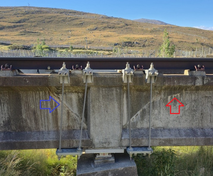
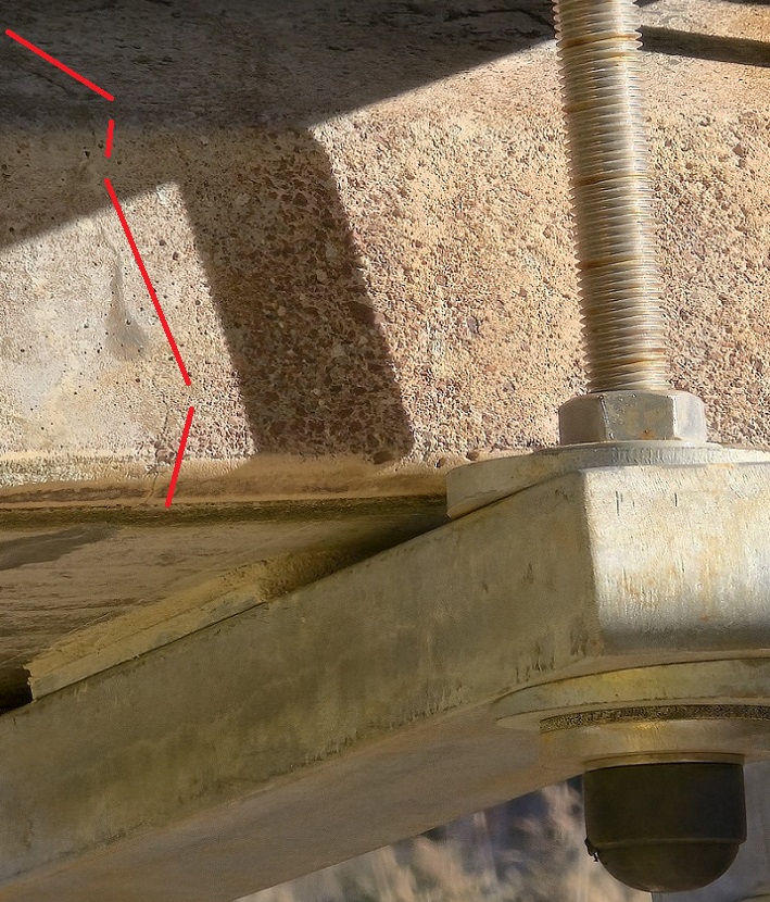
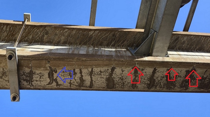
The red arrow indicates a calcite bleed and a crack in the “I” beam! That is likely to require more beam strengthening by further brackets in due course. Again, the L/H bracket on the insitu joint shows a lack of understanding of the repair design. To stabilise the brackets the left-hand studding (blue arrow) should have been through the middle hole of the three in the base plate. (Moving the top bracket to the left would put too much stress on the end of the insitu joint).
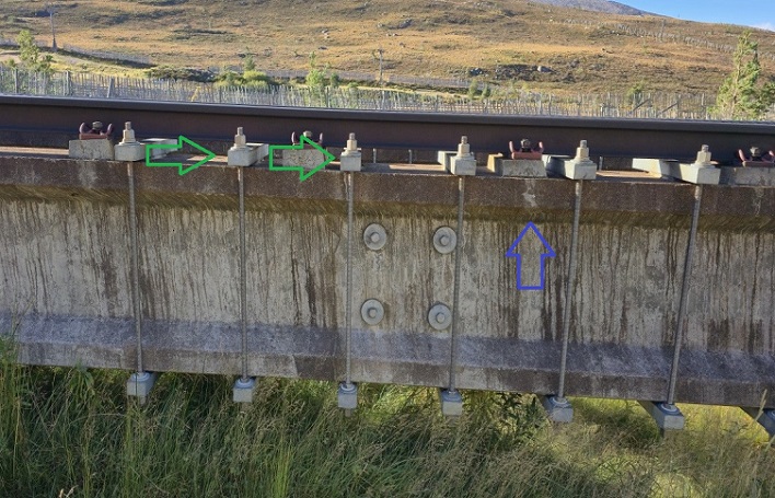
This photo shows how the brackets around the I-beams are designed differently and use metal bars at top and bottom instead of brackets and plates. The top flanges of all type 2 & 3 “I” beams are wider than the bottom ones. This means the metal studding slopes inwards from top to bottom and tapered washers (green arrows) have to be fitted under the nuts to compensate for the angle.
This again takes a degree of understanding from those fitting the brackets about how washers work. The tapered washer on the top bracket should have the thick edge facing in so it faces in the exact OPPOSITE direction to the one BELOW on the bottom bracket where the thick edge should face out (see below).
Yet more complications!
You can also see in the photo below TWO flat stainless washers under one nut when ONE will do the job
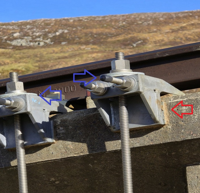
This photo shows how the bottom metal bar, tapered washer, flanged bush and nut with capping should be fitted (bottom arrow). The nut, plastic washer and tapered washer on the top of the metal bar are superfluous only serving to complicate the fitting of the brackets. The plastic washer has probably been damaged by someone trying to tighten the nut with a spanner contrary to the Stage 7 fitting instructions…HAND TIGHT……………..but it was pointless as the nut was superfluous.
Also compare the size of the upper nut with the one in the next picture – more evidence that it was superfluous!
The next photo is of Pier 52 and the beams on either side:
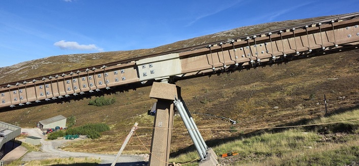
The downhill “I” beam brackets have ALL been fitted with black plastic caps but the uphill long lengths have no such no protection. We gave another example in August (see here– third photo)
It is not possible to see from this photo but on the 4th length of studding on the uphill side, a superfluous nut is 100 – 150 mm up the studding. Remember the post (see here) showing it was loose nuts which led to the closure of the funicular again in August 2023?
Further cracking in the concrete
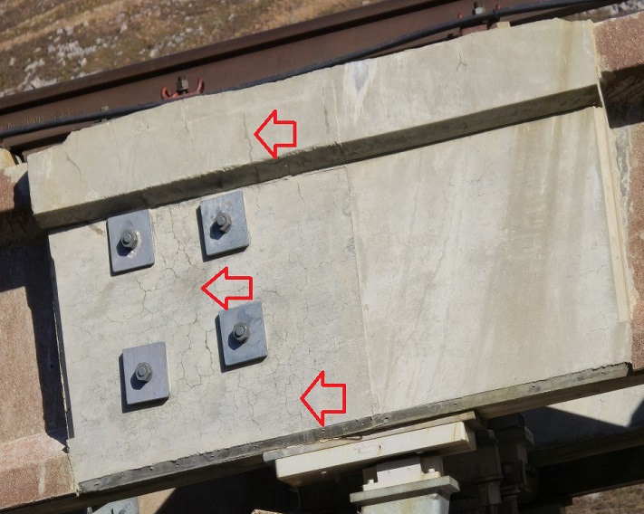
Note all the spider cracks on the left side of the new concrete.
The dark patches on the underside of this beam show either cracks or in places where the rebar (metal inside the concrete) strengthening is exposed. Several of the cracks, including the three arrowed in red, are travelling up the flange edge with the left one appearing to continue into the web of the beam. Rather than repair should this beam have been replaced?
Post 9 in this series will give a possible explanation as to why the strengthening works have gone wrong.

Graham has done a first class factual account of the the conversations he had with Gordon and myself after we visited the day after it recently opened. The Cowie remedial design was meant to be a permanent fix to the the flaws in design and building of the initial very poor design and even poorer construction. It was initially to be done in the period of the initial contract period of the Balfour Beatty, at a cost of £5.5m. Instead it has taken a years and a half more and the cost to BB and HIE must have escalated significantly. HIE turning down yet again the Cowie’s initial suggestion of steel beam replacement, like the initial decision in 1998 is to the detriment of the Funicular Railway and will be the cause of it’s rapidly approaching demise. The seven stage process outline in Graham’s account, although correct is fraught with difficulties and because each group of rods being tensioned to the 7 or 5 tons simultaneously it requires heavy hydraulic jacks that are cumbersome to use and impossible without scaffolding. It was also obvious from our visit that there were “Strike Marks” on a few of these groups to presumably indicate that they had indeed been tension to the requirements of the Cowie design, these strike mark could have been use as an indicator but there are all too few of them to be relied on. I have great difficulty in understanding how the six monthly inspections outline in this article will be conducted without scaffolding being almost permanently erected. It therefore calls into question how the inspection that declared the railway to be safe to open was done and what that inspection amounted to if the tensions were not checked. This supports the conclusion I have come to that the design and even more so the installation is too complicated. The other issue Graham has rightly raised is the condition of some or all of the concrete beams. The original Cowie design stated that the beam deflection was out with the permitted limits, but they did not have any real concern about this. This acceptance came as a bit of a surprise given the state of the beams on site. The other associated issue was that these beams were designed as continuous over the supports and in fact were not built that way, thus the Cowie tensioning and recasting of the insitu cast joint over the supports. Had these beam been made continuous, with temporary props at mid point they would not have deflect so much. Unfortunately they have and this deflection adds to this the state of the beams where the rusty shear stirrup are staring out of the underside of the beams with next to no cover with cracks emanating from them and travelling up the web leads me to that they a well beyond their useful life. There is an Audit Scotland committee in the coming weeks, it is a follow on from previous Reports and is attempting to fill gaps in them. What I would recommend is that they request the inspection team to present to themselves to the committee and address some of the concerns that exist by allowing the Funicular to open recently. There is now only questions that needs to be addressed given the sad story of the incompetence of the owners and it’s history is “Is the Funicular Railway safe to use and how long it will last in it’s current form?” My personal view is that this is measured in months not years with a rapidly increasing maintenance cost!
I do the odd bit of car mechanic-ing, & I’ve seen a fair bit multi stage torque control & angle tightening instructions, but those really take the biscuit! Plus you’re outdoors up a mountain, on scaffolding, wet/tired, & with several crews by the looks of it! Chances of a decent % of the fittings being “out” of install spec is very high!…From what I know of building/construction those spider cracks need watching, & that amount of steel “strapping” is diabolical, & proves how inadequate the original design was! I mean its not as if its a grade1 listed 200yr old building!
A great exposure of the continuing structural problems with the funicular, especially as the issues are somewhat complex. What needs to be asked is just how long will this failing structure last and at what maintenance cost? John Carson, in his comment above, believes the structure life should be measured in months, not years. Just to remind everyone, the full business case approved by the Scottish Government back in 2020 was heavily based on the assumption that the repairs would extend the life of the funicular by another 30 years! It is very clear that this assumption is and always was far from accurate. If this 2020 business case had been honestly presented, the worst financial case option would have been this repair option – NOT the best!