This post takes a look at Highland and Island Enterprise (HIE)’s response to Gordon Bulloch’s Freedom of Information request of 05/12/2024 (see here) and attempts to explain what went wrong with the funicular repairs.
As I said in the last post (see here) both COWI, the design engineers for the funicular, and Balfour Beatty, the construction company, are international reputable companies. Civil engineer John Carson, the civil engineer on the Skye bridge project, has looked at the COWI reports and concluded that the reports and the design of the repairs was probably the best anyone could do given the flawed design of the funicular structure. If the strengthening regime was the best solution to keep the funicular going then what went wrong?
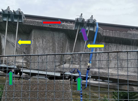
(1) Part of the answer lies in the photo above of the brackets around the insitu joints.
(a) The original design for the strengthening of the insitu joins was for FOUR “channel sections”, two at the top and two at the bottom. At some point this design was changed, as can be seen in the photo above, and not for the better. It only takes ONE nut to lose tension and the whole bracket becomes unstable and ceases to do it job. It is also more awkward to tension all four lengths of studding to the same tension so, whoever changed the design, built in a fault which made it more likely for the repairs to fail!
(b) Because of the position of the rail fixing (red arrow above), the right hand bracket on the downhill side of the in situ joint has had to be fitted with both lengths of studding sloping to the right. It is difficult to be 100% certain if the studding on the left hand and uphill bracket is sloping to the left although it looks like it is. Both should have been fitted perpendicular to the insitu joint and beam for the tensioning to hold the whole structure together effectively.
The downhill bracket has been fitted by a team who apparently did not understand the strengthening regime and why the studding should have been perpendicular in relation to the insitu and the “I” beam. That begs the question where was the supervision and the quality control?
(c) What can’t be seen from the top photo is that the single bottom plate, which replaced the original design of two brackets, has 3 pairs of holes for the studding, not just the two that are in use.

Had the studding been fitted to the middle and right hand holes it would then have been vertical and exerted the tensioning as intended. In this position the bracket could not have moved because it is butted up against the rail fitting on top and by the bearing plate at the bottom.
Contrast that with the sloping bracket(s) where vibration from the funicular may have shaken the bracket to the point where it slid down the “I” beam thereby reducing the tension that was so necessary for the bracket to do its job. That would explain the loose nuts that led to the funicular being closed again
(2) Further problems with the bracket fitting.
There were three types of “I” beams (see here) used in the construction of the funicular and the flanges of the type 2 and 3 “I” beams are wider at the top than the bottom.
Type 1 “I” beam. Top flange 340mm wide, bottom flange 340mm wide.
Type 2 “I” beam. “ “ 400mm wide, “ “ 340mm wide.
Type 2 “I” beam. “ “ 500mm wide, “ “ 340mm wide.
The concrete flanges at the top of the insitu blocks are wider still, although also only 340mm at the bottom where the lower bracket sits. This means the studding on the Type 2 and 3 ”I” beams slopes inwards from top to bottom. As a consequence tapered washers are required to ensure the nuts sit flush and are correctly tensioned. The following information from the website of GSS Fasteners ltd explains why tapered washers are necessary on all but the brackets fitted around the Type 1 “I” beams

“It’s also important to select the correct angle for the taper washer. The angle of the washer should match the angle of the surfaces being joined to ensure proper alignment and load distribution.”
“Taper washers may seem like a small component, but their purpose and impact on the stability and reliability of bolted connections are significant. By providing better alignment, load distribution, and protection for the materials being joined, taper washers play an essential role in ensuring the success of many construction, engineering, and mechanical projects”
Note the 2nd para [my emphasis]. Because there are at least three different widths to the top flanges, two on the “I” beams and at least one on the insitu joints, to do the job and achieve the result as intended there must be at least three different angled, tapered washers.
Getting the tension right is even more complex because even fitting brackets to Type 1 “I” beams requires two lengths of studding, six nuts, three for each length, and EIGHT (flat) washers, four for each length.
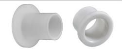
Each length of studding has a flanged, plastic or similar material, bush at the top and a plain bush between the bottom two nuts, the purpose of which is to protect the galvanised fixings of the brackets from the stainless studding. This type of bushing requires a washer above and below to protect the softer material. This clearly visible on the studding fitted in the photo below.
Each bracket on the Type 2 and 3 “I” beams will require FOURTEEN washers, SIX of them tapered to allow for the different angles of the studding and EIGHT FLAT washers to protect the upper bushings AND the galvanising on the tapered washers. At least two of those flat washers will need a larger hole to allow the bush to go through them.
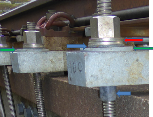
This photo shows how the fixing of the brackets was all wrong. One of the two stainless steel washers (red arrow) should have been above the bushing flange and the other between the flange and the tapered washer so the lower washer is in the wrong place! Moreover both tapered washers should face in the same direction but they don’t (it’s the tapered washer on the left that has been fitted wrongly).
What is clear from this is that the metal brackets were fitted by someone people who didn’t understand what they were supposed to be doing.
The next photo is of the lower part of the studding:
 The upper nut is only being used to hold the studding in place on the bracket while assembly is taking place so being smaller makes sense but it further illustrates the complexity of the fitting process. It is not possible to determine from the photo what has been used below although it should be two tapered and two flat washers.
Imagine the scenario. The repair teams now have a choice of possibly different sized nuts, two different bushes and at least three different sizes of tapered washer.
Fred. “Hey Barney, what have you got in your tool bag?”
Barney. “Loads of washers, nuts and some bushes!”
Fred. “Pass some of those big washers over I’ve run out. Any ones will do”.
What could possibly go wrong?
“A picture is worth a thousand words”.
Look at those pictures again.
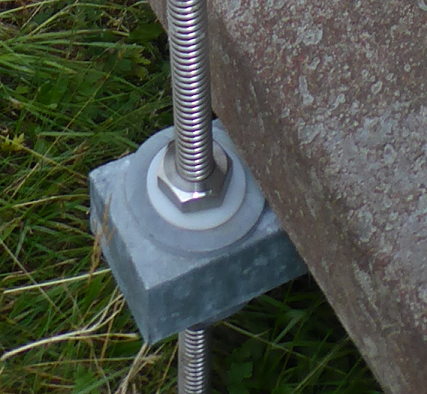
The next picture shows that these issues had not been properly understood when the repairs to the repairs started.

The top two stainless washers are not fitted to protect the bush flange and there are TWO tapered washers! If that was the finished job BEFORE the funicular re-opened in February 2025 then how long before it all goes wrong again? The workmanship is shocking.
As a result of HIE failing to get either repair job done properly, yet more good money has followed what was always a bad investment. Perhaps Highlands and Islands Enterprise and Cairngorm Mountain (Scotland) Ltd will now re-assure the public that every single one of the brackets on the funicular structure have been fitted and tensioned correctly? If they don’t/won’t, it looks like we might have to wait for an accident before HIE/ CM(S)L take notice and admit that they got the repairs to the funicular totally wrong.

It does shine a light on the capability of HIE as the managing agent in respect of managing such an asset. It’s a civil engineering structure and an operating piece of transport infrastructure- why is this multimillion pound public asset being managed maintained and developed on an ad hoc project basis? There must also be liabilities that sit with them under CDM which have only been caught at the last minute external body checks??!?!? Supervision?, Clerk of works?