Following on from my last post (see here), which looked at whether vibration from poorly maintained rails could have caused damage to the piers supporting the funicular, this post focuses on the concrete parts of the structure, especially the ends of the “I” support beams and the in-situ blocks. The “I” beams are described as such because of their shape, ![]() , when viewed through vertical section while the “in-situ” blocks are so-described because they were poured “in situ” (rather than pre-cast like the “I” beams).
, when viewed through vertical section while the “in-situ” blocks are so-described because they were poured “in situ” (rather than pre-cast like the “I” beams).
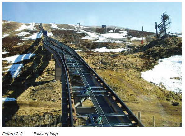
The picture above is probably the best one showing the layout of the tracks, including the passing loop, but also shows two piers referred to below. Pier 52 is the one showing to the left of the track with pier 51 just visible between the lower pulley and the next two. The photo also shows how the funicular destroyed Cairn Gorm’s iconic White Lady ski run, one more reason why it should never have been built and should be removed asap.
Examples of what appears to have gone wrong with the insitu concrete blocks.
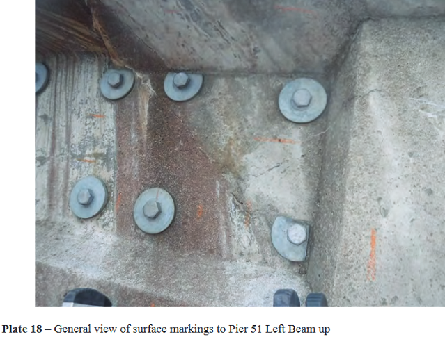
The picture above shows the join between the in-situ block and the left side (looking up the hill) of the concrete “I” beam of Pier 51. Although it is unclear exactly what is going on here as the photo has been taken so close to the pier, it provides ample evidence of the poor workmanship so often referred to in the COWI and ADAC structures reports on the state of the funicular. It looks as though the mould for the concrete joint, which is usually made from plywood and is called “shuttering”, has been poorly constructed. As a result the surface to the right of bolts is sloping, rather than vertical, and appears warped (a consequence of using an old piece of plywood). While some of the concrete may have been patched later, it also appears to have almost covered the bolt holes used to secure the bracing steelwork between the beams (visible in the top photo). At least one washer under the bolt heads has had to be cut with an angle grinder to get it to fit.
There are also several marks showing. Some may be cracks but they could also have been caused by markings on the surface of the plywood when the insitu block was poured!
Compare the quality of the shuttering work on the insitu block illustrated above with that in plate 24 (pier 53) below!
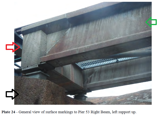
Note how the edges in the insitu block are straight and “clean” compared to those shown in plate 18.
Apart from the shuttering, there is evidence from the photos in Plates 18 and 24 that not enough care was taken when the concrete was poured to create the in-situ block, as shown by the surface markings. This is easier to see in plate 31:
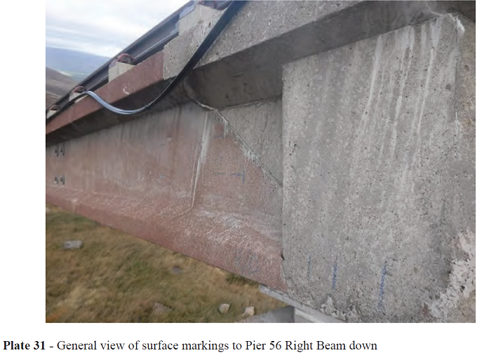
These could have been caused by the concrete not being vibrated enough with a vibro-rod/ poker or from cold weather.

Air has to be removed from the concrete pouring to enable it to reach its design strength!
While the funicular was built over the summer months the COWI report says that the temperature range on Cairn Gorm can vary from as low as -27deg.C to +29deg. C, a range of 56deg. C and that a temperature of -9deg.C had been recorded in July 2018!
I am reliably informed that when construction recommenced in April 2001 Cairngorm was still ski-able. The foundations, poured the previous summer, may not have been subject to such a range of temperatures, as the ground around would help to stabilize temperatures and protect the foundations from the elements, but the same cannot be said for the pouring of the in-situ concrete blocks and could account for the damage. Wind and direct sunlight are also variables that should be considered.
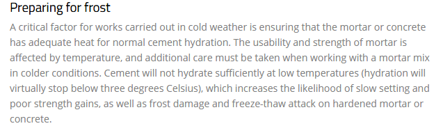
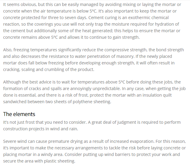
Concrete takes at least 24 hours to cure in normal conditions, which are rarely encountered on a mountain like Cairn Gorm, so except in very settled weather protection would need to have provided in the form of heated blankets or temporary shelters. The following article, taken from a magazine called Probuilder, explains the problems and remedies in more detail.
The in-situ concrete used at Cairn Gorm was made in the car park area and then carried by helicopter to where it was needed. This raises another potential issue. There would be times when the helicopter lift would have a shortage or an excess of concrete to fill one of the moulds and an in-situ joint may not have been finished in one pour. This would result in partial setting of the concrete already in place leading to a poor joint. The next picture, especially in the lowest part of the in-situ concrete block, shows what that might look like:-
Although this apparent difference in the composition of the concrete, which may have weakened the whole structure, could also be caused by ineffective use of the vibro-poker!
Returning to Plate 24, observe that the end of the precast concrete “I” beam is angled, sloping forward from the top edge to the bottom. This gives a much superior join than a vertical joint. But if you look at the plate which carries the top half of the sliding bearing, that plate only supports the last 50 – 75cms of the end of the “I” beam and, in some cases, due to poor construction, not even that:
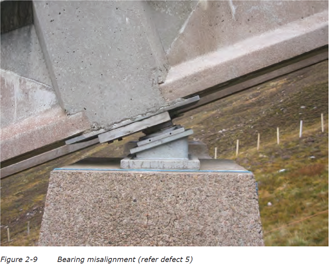
Note the gap between the two beams and the support plate above the ancon bearing. It appears that the concrete poured to form the insitu block above has partly filled the gap.
Aside from the workmanship, the design itself is in my opinion poor for two reasons:
(1) The plate should have extended far enough to support the “I” beam from the leading edge of the top flange. The lack of support may account for the damage to the lower flanges of the “I” beams, damage that appears at several different piers.
(2) The plates should also have rounded corners and edges to prevent stress points.
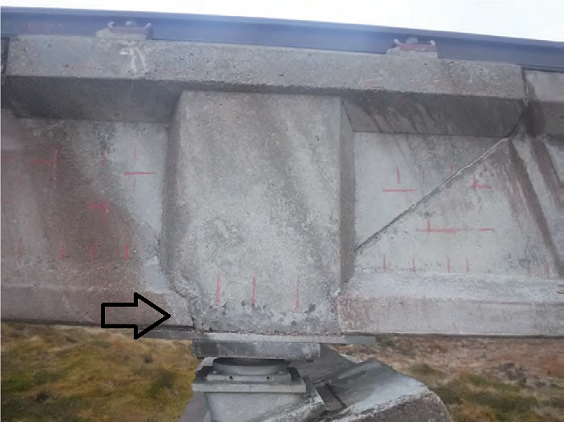
The likely consequences are illustrated by the photo below:
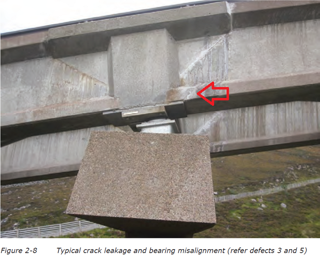
The red arrow marks what appears to be a crack leading diagonally upwards from the edge of the plate, just where you would expect this to happen if too much weight was placed on an inadequate sharp edged support.
The planning application for the funicular stated that replacement of the Ancon bearings below the plates is part of the repair work, so it will be interesting to see if this includes new longer plates. If so, all the in-situ joints will need to removed as the support plates have concealed vertical sections that project into the concrete above. That could help explain why the cost of the funicular repairs comes to an extraordinary £16.16m.
The significance of the faults in the concrete
While it is hard to believe that a company like Balfour Beatty would agree to undertake repair work that could damage its reputation, the big question to be asked is “Are the repairs guaranteed to last for thirty years, the timescale used to justify Highland and Island Enterprise’s Business case?” (see here). There are serious questions about that because the causes for the structural failure do not appear to have been investigated and, without that, no-one can be confident as to how long the repairs will work!
While HIE still appears to be in the process of a legal case concerned with the “design and build” aspects of the funicular railway, many of the problems with the concrete structures may stem from the £2m cost cutting exercise imposed by HIE on the contractors 20 years ago in order to bring the funicular into budget. If so, we are all paying for that now and even more reason for HIE to come clean about what has really gone wrong with the funicular.
More to follow next week!

You state:- “Air has to be removed from the concrete pouring to enable it to reach its design strength!”. For utmost clarity:- You want the “right” air in the mix, as there are two types of “air” in concrete design, micro air bubbles (0.5mm dia) & entrapped air voids. Micro air bubbles increase the plasticity/workability of the mix making it easier to pour & thus requiring less water in the mix. They also increase the frost resistance of the concrete by acting as pressure relief valves when the concrete is frozen & water saturated, by cushioning the expansion effect within the concrete. Air entrapped voids on the other hand you DO NOT want. These are caused by the larger sizes of the aggregate in the mix preventing the “fines” of the mix (sand/cement) from flowing into corners, nooks & crannies when the mix is poured. This usually occurs at the bottom of reinforced & deep section concrete when there has been inadequate vibration of the mix (using a vibro-poker) when the concrete is poured into the mould/shuttering. Also, by using a vibro-poker to get rid of entrapped air voids, effectively “compacts” the concrete mix, making it “knit” & be more dense & more impermeable. This latter entrapped air void problem is what you are referring to, & is clearly evident in the “blowholes” & “honeycombing” on the finished surfaces shown in the COWI photo no. 38 of pier 69, on page 293 that you include above. Basically, shoddy workmanship!