
Following on from my post about the metal brackets being use to hold the funicular together (see here) this post takes a further look at WHY the concrete “I” beams have been disintegrating. It is now five weeks since my walk up the funicular and discussions with staff who told me the funicular would be re-opening in five weeks time and the passing loop is still surrounded with scaffolding.
A crack in the concrete
The ADAC Structures report dated 15/07/2017, obtained by an FOI Request, reported:
“2.2 A crack was clearly seen running along the length of the beam positioned at about mid height of the top flange. It appeared to extend from the lower end up to about mid span. See appendix B for a sketch and photo showing this.
2.3 Some comment on observations:
- The writer has been carrying out annual inspections for the last three years. This feature was observed for the first time during last year’s inspection.
- The crack is evident on both sides of the beam at the same height and over the same length.
- The crack is particularly evident due to calcite bleed, showing up white. This was seen as significant at the low end, diminishing along the length.”
This crack was “observed for the first time” in the 2016 inspection when it was described as being a few cms. long. By the 2017 inspection it had increased to almost 9m! That is more than a crack, it is the top layer of concrete above the reinforcing rebars inside the beam delaminating. Was this caused by water ingress and rusting of the rebar at the insitu joint?
When water gets into a crack and then freezes it will cause damage at that point. The subsequent freeze thaw process, which in a mountain environment could happen several times a day, will gradually weaken and destroy the concrete joint. Eventually the water will work its way through a joint and when reaching the steel rebar will cause corrosion and then potentially delamination along the length of the rebar. Vibration caused by the train will exacerbate the situation.
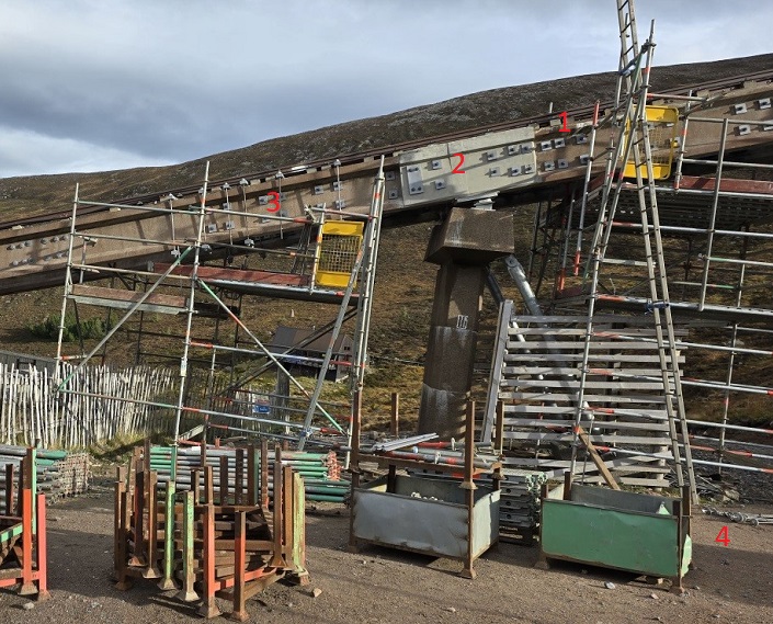
That this may be the case is shown by the extensive repairs that have taken place on the insitu joint above Pier 51:

Cause of the crack
The ADAC Structures report explains the crack as follows:-
“5.2 It is thought that the problem is a latent defect within the original fabrication of the beams, most likely due to a cold joint within the concrete pour”.
That is one possibility but these “I” beams were manufactured in a factory where conditions and work practices should have been strictly controlled. During and after manufacture there would have been several inspections of the “I” beams:-
(1) Testing of concrete at the factory to make certain of its suitability,
(2) Inspection of the “I” beams after being removed from the mould,
(3) Inspection of the “I” beams when they arrived at Cairn Gorm, and,
(4) Any problem should have been noted when the beam was being fitted on the piers.
For ADAC to be right FOUR opportunities to identify a problem in any of the “I” beams would have had to have been missed. There is a more likely explanation.
The COWI report of December 2018, also obtained through FOI, stated:
3.2 Construction sequence
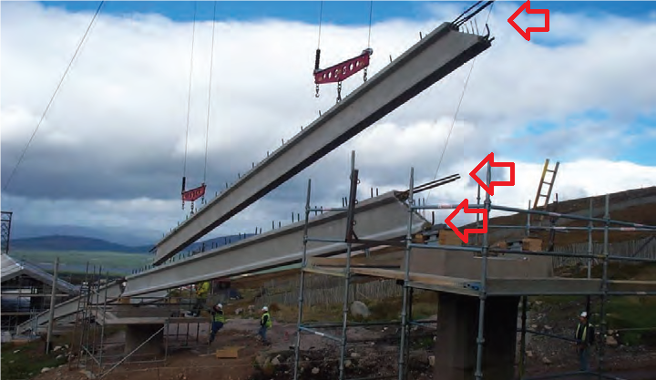
The sequence of construction shown in construction photographs shows that the precast beams were installed as simply supported spans before the insitu concrete at piers was cast. Therefore under dead loads there would initially be sagging moments but no hogging moments. This could change in time due to concrete creep and differential settlement.
When COWI states that the Type 1 “I” beams “were installed as simply supported spans” this means that initially their entire weight was held by the piers on either side and, in the case of the funicular by a small metal plate.

By contrast to a simply supported span, if the beams in a structure are joined together AND tensioned they then create a “continuous beam” whose weight would be distributed over the entire structure. This difference becomes important when a dead weight – such as a full funicular carriage –exerts force on one beam. If the beam is only simply supported rather than forming part of a continuous structure the risk of “sagging moments”, which cause the beam to crack, increases,
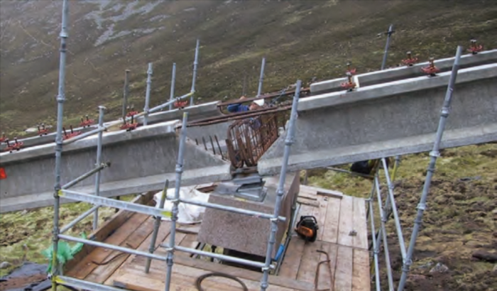
The picture below shows the rebar protruding from the concrete. The lengths of rebar protruding from the top flange were used to connect one “I” beam to the next and hold them in place:
There are a number of ways to join those top three lengths of rebar to the rebar in the next beam, the most common being:-
(a) tying or lapping them together. Lapped joints are usually held in place using T8 rebar so that there is a gap between the two lengths being joined. This allows the concrete in a pour to fill the gap between them.
(b) using mechanical couplers “Lapped joints are not always an appropriate means of connecting rebar. The use of Ancon Reinforcing Bar Couplers can simplify the design and construction of reinforced concrete and reduce the amount of reinforcement required”. (Quote from Ancon)
(c) Welding. This is a challenging way of joining overlapping lengths for a number of reasons:-
(i) The heat produced by welding alters the tensile strength of the rebar, and,
(ii) There is a possibility that when the concrete is poured around those bars that an air gap exists under the bars i.e. the concrete is not in full contact with the rebar thereby decreasing the strength of the join.
Even after a beam is connected to the next one using an insitu joint, in civil engineering terms it remains a simply supported beam if its entire weight sits on the piers at either end and ONLY becomes part of a continuous beam if couplers are used, effectively post tensioning the structure. While lapping and welding therefore holds supported spans in place, only the use of the correct Ancon, or similar, coupling strengthens the joints and put them under tension changing the beams from simply supported to continuous lengths.
The initial cracking of the beam at Pier 51 could therefore have been caused by sagging of the beam under the train’s weight because it was not properly tensioned and that would explain all the stainless steel brackets.
How were the funicular beams joined?
Unfortunately, as explained in the COWI report, many of the original plans were lost and it is unclear if the funicular was intended to be one continuous structure.
It does seem, however, from the “Condition report into concrete support structures for Funicular Railway” (November 2015) .that ancon couplers were used around the passing loop:
“4.1 The writer inspected the items listed in the schedule at item 3.1 of this report. It was reported that the installation had been completed in 2001, making it 14 years old. The general condition was thought to be poor for a structure of this age with wide spread minor deficiencies giving a general impression of possible poor quality control during the construction phase”.
“4.5.3 Description: This item, in certain locations, gives the greatest cause for concern. The construction drawings made available for the insitu area are stamped “preliminary” and as such no firm conclusions can be based on them. However they show a system for mechanical coupling of the reinforcing bars to provide continuity at some locations. One of these couplers is specified as an Ancon PB32, which involves an onsite grouting operation, this would be susceptible to poor quality control. For operational reasons close quarters examination of this joint as a train passes was limited to one location, pier 56. Here the crack was clearly seen opening then closing again, by an estimated 1mm, as the train passed. The concern here is that the coupler may have failed leading to a redistribution of stress to the midspan of the beams that they were not designed to carry. Ref photos [9], [10], [11].
Location: Opening of the joint line between the precast beams and insitu fill. This was wide spread although not universal.”
[ N.B. My underline and colour change].
Note the importantce of the couplers: “The concern here is that the coupler may have failed leading to a redistribution of stress to the midspan of the beams that they were not designed to carry”.
I have, however, spoken to the welder employed on the original build and he has claimed that Type 1 beams were welded together in which case they would remain as “simply supported”. How many is not clear.
If the “I” beams remain “simply supported” the industry standards, as advised to me by both a lecturer at a rail engineering college and a civil engineer, would be for the beams to be 10cm deep for every 1m length, i.e. they shey shold be 1.6 to 1.8m deep, depending on the length of a beam, NOT the current 0.8m! In other words, where the protruding rebars have been welded together, rather than being properly coupled and tensioned, or the coupling has failed due to poor quality control, the likelihood of the beams failing will have increased significantly.
Conclusion.
John Carson, a civil engineer who has been in contract with parkswatch, has today had an interview published with the P & J (see here) and is adamant that concrete should never have been used in the funicular construction. His opinion is that the civil engineers would not request a change in materials and that the whole structure is inherently unsafe because it wasn’t built properly. Para 4.1 of the ADAC Structures report, written when the funicular was 14 years old, appears to confirm this observation: “The general condition was thought to be poor for a structure of this age” . It is now 23 years old, another 9 years of deterioration!
Can HIE, CM(S)L and others afford to ignore Mr Carson and other civil engineers who now appear prepared to speak out? Given the safety implications that could be classed as reckless at the very least. Will HIE, CM(S)L, DfT and others now take notice and order a full investigation into the funicular before the track collapses and the consequences of that happening?
The major question that still needs to be answered is IF THE ORIGINAL DESIGN WAS FOR A STEEL STRUCTURE, WHO ORDERED OR REQUESTED THE CHANGE FROM STEEL TO CONCRETE WHICH HAS COST THE TAXPAYER £ MILLIONS AND CAUSED CONCERNS OVER PUBLIC SAFETY?
There are still people around who could help answer this. For example, at the time Morrison’s tendered for and built the funicular they had a chief civil engineer Michael Martin OBE, who was involved in the construction of the Kessock bridge and then with Morrison’s on the construction of the Dornoch Firth and Kylesku bridges, two very successful projects, but there is no mention in his Wikipedia entry of any involvement in the Cairn Gorm funicular! This gentleman transferred to Anglian Water Group (AWG) when they purchased Morrison Construction in 2000, a year before the funicular build was finished, and subsequently worked for Galliford Try, who purchased Morrison Construction from AWG in 2005.

It’s time for those who were involved in the decision to change to concrete to come clean and blow the whistle if they were put under pressure to do so. This whole sordid affair needs to fully investigated and those responsible for this MASSIVE waste of tax payers’ money must be held to account.
It’s worth listening to this interview with John Carson on BBC Scotland’s Good Morning Scotland programme. https://www.bbc.co.uk/sounds/play/m0024vrn 2:50:12 to 2:55:24.
“It’s never going to be safe for people to travel on.”
“It’s inherently flawed.”
“The foundations were never built properly.”
I’m not a Civil Engineer, but I do know more than the average person about reinforced concrete, steel, building design, etc. as I’m a qualified Architectural Technologist (Technical Architect). Reinforced concrete beams can & have been done properly on many road bridges etc.. However, I have always been sceptical about the CGM funicular design as the beams are rigidly joined to each other over the top of each of the piers, with only a hand full of actual breaks (anchor blocks) separating the very long joined sections. This creating problems for the thermal expansion & contraction that will occur in localised sections, e.g. part of the track can be in a total shade for many months of the year, whilst other sections can be in more sunlight. This before you discuss the loading from the carriages causing problems of beam flex over the pier tops! Of upmost importance is the plain fact the design was seriously flawed from the beginning & not up to the job &/or the build quality was sub-standard. This proven by the vast amount of external strapping & reinforcing that has had to carried out to the beams, let alone the underpinning & additional external propping up of many of the piers, & all in less than 25yrs & we are NOT in an earthquake zone! Also, its not as if the mountain has repeatedly slid like the A83 “rest & be thankful”…!!!
I have been concerned for sometime with the observed ‘rotation’ of so many of the concrete support pillars. This rotation seems to be due to the pillar bases moving downhill, whilst the tops of the pillars are fixed to the concrete beams. It appears that at the most there are only three pillars in the 90 odd pillars which are fixed to bedrock, the rest essentially ‘float’ within the glacial till within Coire Cas, It is a known fact that geomorphological creep can and does happen in such circumstances. Massive boulders (sometimes termed erratics) have been observed to very slowly creep downhill over a period of years. It is very likely that this process has caused the ‘rotation’ of the concrete support pillars. The underpinning and external propping carried out on numerous pillars will only slow up the rotation as these larger foundations are still ‘floating’ on the glacial till. The erosive effects of significant quantities of groundwater around these foundations should also be taken into account.
Significantly, very little geotechnical investigations were conducted before the funicular was built in 2001, which in my book is negligence on behalf of the designer and constructor. Even when COWI reported on the structural failures back in 2018-19, again only a rudimentary geotechnical investigation was conducted by COWI.
I agree, landslides like those that have occurred around the A83 are very unlikely in this case, but geomorphological creep continuing to damage the structure cannot be ruled out.
Gordon Bulloch…..Your comment raises more questions:- If it is known that the area has massive boulders & is still “settling” from the last Ice Age, why did they build a funicular with long lengths of beams rigidly joined, & effectively build the piers on the boulders/till? Surely the common sense approach would be to place loads of flex points (one at every other, or every pier top) to “take-up” any movement. Or build a system with lots of flex in it, say towers with cables between them…hang on isn’t that a chairlift/gondola?!!
John Carson has simply articulated what many respected Engineers have been saying for long enough: “this ain’t going to work”
He’s gone further though and stated it is not going to be safe. Game over I would suggest…
Even If HIE somehow manage to get the remedial work completed and signed off by the regulatory authorities (massive IF) what maintenance regime and ongoing costs are forecast to keep the railway safely operating – and what life expectancy can the taxpayer expect from this “asset” in the go -forward?
Of course they haven’t a clue because this cannot possibly be measured! HIE have painted themselves into a corner because they are preoccupied with covering up one bad decision after another.
Seriously time to pull the pin on this one.
On maintenance regime. The new brackets themselves are secured with c 4856 lengths of studding and19424 nuts! That does not include all the new plates fitted or the extra beams at the passing loop. It’s an impossible task.
There cannot be a structure in the UK that is so badly built still in public use. The certifying authority should be put on notice as to it’s state and it’s certification removed immediately.
I will leave the technical aspects of this to those who understand from industry experience the crackpot lunacy of this changed project. What gets me is the political similarity between this – “original plans lost” – and the frequent loss of memory amongst other elected people on other important affairs . https://www.spectator.co.uk/article/whats-going-on-with-nicola-sturgeons-memory/ – It may be coincidental but memory loss seems to be the Scottish Govt’s default defence. How on earth plans can be simply lost beggars belief.
As for the original project proposal: it would seem that the RSPB’s tunnelling from Rothiemurchus would have been far, far better and the original cost argument’s against every other idea other than a funicular was very poor decision-making when the real experts in mountain transportation were never going to be involved. Dopplemayr -https://www.doppelmayr.com/en/ – could have planned, produced and provided full maintenance of either a funicular or a fully tunnelled operation but the introverted ‘we can do this ourselves’ attitude that has so often condemned Scottish infrastructure projects to difficulties has brought us to this point on Cairngorm.
My preferred option would be for the structure to have a catastrophic failure (without loss of life or injury) and for the whole lot to be compulsorily removed by Morrisons under their own cost. The perhaps our mountain environment can be re-set and better managed to include uplift which enables a well constructed business to run and operate a potentially worthwhile attraction and facility. The current goons and NP need to be kept well away!
This article highlights the challenges of using concrete in extreme environments like the Cairngorms. It’s an important discussion on balancing durability with environmental impact in infrastructure projects. Check out more about https://www.clearwaterflconcretecontractor.com/stamped-concrete.html